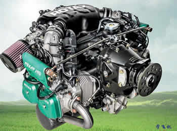
 yibiao
 kingair
 s0
s0
Preparation:
Before the propeller gearbox is removed, the work described below must be carried out to identify any further malfunctions:
- General visual inspection, see current Maintenance Manual Line (MML) for the respective engine type.
NOTE: Particular attention is needed in the corresponding zone of the crankcase and gear- box mounting screw holes, including the dowels. If any cracks/abnormalities are found, the engine must be shipped to any Rotax approved overhaul facility for repair/ overhaul.
- Remove the surrounding assemblies, see current airframe and propeller manufacturer’s
instructions.
- Remove the gearbox oil line assy, if installed.
-Remove the external alternator, if installed.
Step | Procedure |
1 | Remove the gearbox and drive gear. See current Maintenance Manual Line (MML) for the respective engine type. |
2 | Perform a crankshaft run-out inspection on the PTO side. See current Maintenance Manual Heavy (MMH) Chapter72-10-00 for the respective engine type. |
3 | Perform a crankshaft distortion inspection. See current Maintenance Manual Heavy (MMH) Chapter 72-00-00 for the respective engine type. |
4 | If any of the above measurements are exceeded, the engine needs to be shipped to any Rotax approved overhaul facility for repair/overhaul. |
5 | If the above measurements are within limits, perform service of the whole gearbox in accordance with current Maintenance Manual Heavy (MMH) Chapter 72-10-00 for the respective engine type. |

Step | Procedure |
6 | Perform NDT inspection of the propeller shaft (1), gear set (2) and gearbox housing (3). For 912, 912 i and 914 (series), also perform NDT inspection of the dog hub (4) or clutch hub (5). NOTE: In the case of 912 i, 915 i and 916 i engine series, the gearbox housing has an electrophoretic coating (black) that does not require removal in order to perform the crack detection. |
7 | If cracks are detected on any of these components the parts need to be replaced. NOTE: The gearbox mounting screw holes, dowel holes and roller bearing fixa- tion screw holes must be carefully inspected for any cracks or abnormal- ities. |

1 Propeller shaft
2 Gear set
3 Gearbox housing
4 Dog hub
5 Clutch hub
Step | Procedure |
8 | Disassemble overload clutch and damper clutch. See Chapter 72-10-00 Maintenance Manual Heavy (MMH). NOTE: The overload clutch of the 912, 914 and 912i Series, needs to be shipped to any Rotax approved overhaul facility for repair/overhaul. |
9 | Check all given wear limits for the gearbox assy. See current Maintenance Manual Heavy (MMH) Chapter 72-10-00 of the respective engine type section “Inspection” and “Wear Limits”. |
10 | Replace all 100% replacement parts in accordance with current Maintenance Manual Line (MML) chapter 05-50-00, for the respective engine type. |

1Oil seal
2 Ball bearing
3 Washer
4 Hex screw
5 Thrust washer
6 Ring half (x2)
7 Roller bearing
8 Oil seal
9 Oil inlet flange 10 O-ring
11 O-ring
12 Sealing ring
13 O-ring
14 Retaining ring
15 Torsion shaft
16 Retaining ring
17Needle bearing
Step | Procedure |
11 | If the rest of the parts are not within given limits or have unusual wear or damage, the parts need to be replaced. |
12 | Assemble gearbox. See current Maintenance Manual Heavy (MMH) Chapter 72-10- 00 of the respective engine type, section “Assembly”. |
13 | Re-install drive gear in accordance with current Maintenance Manual Line (MML) chapter 05-50-00, for the respective engine type. Check the crankshaft run-out. See current Maintenance Manual Heavy (MMH) Chapter 72-10-00 for the respective engine type. |
14 | Re-install the gearbox in accordance with current Maintenance Manual Line (MML) chapter 05-50-00 for the respective engine type. |
Finishing work:
- Install the gearbox oil line assy, if installed.
- Install the external alternator, if installed.
-Install the surrounding assemblies, see current airframe and propeller manufacturer’s instruc- tions.
 粤公网安备 44040302000324号
粤ICP备15064906号 Powered by Xuefeiji X1.0 Code ©2003-2020
粤公网安备 44040302000324号
粤ICP备15064906号 Powered by Xuefeiji X1.0 Code ©2003-2020